Divertor rails
A chicken and egg situation
24 Sep 2018
-
R.A.
In the ideal world of 3D drawings, a component's dimensions are by definition nominal and parts fit together like cogs and gears in a pricey wristwatch. The real world—even the high-precision world of ITER—is different: minute variances during the manufacturing process are inevitable, especially when components are as tall as a six-storey building ...
How can the precise dimensions and positioning of a component—i.e., a section of divertor rail— be determined when the "as built" references for the interfacing systemps are not yet available?
In ITER, the pieces of the machine will not only have to fit together within extremely tight tolerances; they will also need to be aligned with utmost precision against fixed reference points, such as the matrix of metrology targets disseminated throughout the Tokamak Complex.
An added difficulty arises when a reference can only be established once a set of components is completely assembled. The machine's magnetic axis for instance—a paramount reference for tokamak operation—will only be determined after the vacuum vessel is installed and an initial series of plasmas has been produced.
The localization of the machine's magnetic axis, in turn, will determine the position of the 54 cassettes of the ITER divertor situated at the bottom of the vacuum vessel.
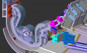
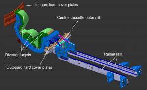
"The 54 elements of the divertor must be aligned with extreme precision—and I'm talking tenth of millimetres here," says Divertor Section leader Frédéric Escourbiac. Divertor cassettes will be inserted by robotic handler into the vacuum vessel through the lower ports. Once inside the chamber, they will be moved along double concentric toroidal rails into their final position.
Once positioned, the cassettes will be fastened on these inner and outer rails. A slight misalignment of the circular railing could result in the misalignment of one or more of the 54 divertor cassettes—hindering operational flexibility and threatening the integrity of the divertor targets which face intense heat and electromagnetic loads from the plasma.
3D drawings provide a theoretical magnetic axis based on a perfect vacuum vessel, perfectly machined and perfectly assembled. But the "as built" reality, which will determine the precise dimensions and positioning of the rails, cannot reproduce this nominal perfection.
Divertor cassettes will be inserted by robotic handler into the vacuum vessel through the lower ports. Once inside the chamber, they will be moved along concentric toroidal rails into their final position.
Engineers are left with a "chicken and egg" situation. How can the precise dimensions and positioning of the rail sections be determined when the "as built" references are not available yet?
The solution comes in the form of statistical models that compute the tolerances of all interfacing systems and take into consideration different scenarios for the localization of the magnetic axis.
This is the basis upon which the rail sections can be manufactured—not completely finalized, but "semi-finished" with extra thickness that will allow for adjustment later.
Once everything is in place—the vacuum vessel has been fully assembled and welded, interfacing systems are in place, and magnetic axis has been determined—a geometrical 3D survey can render the as-built reality with absolute accuracy. "With reverse engineering, we can then customize the rail sections and the interfacing pieces on site," says Alain Durocher, the ITER Organization responsible officer for the divertor rails.
The ITER divertor is designed to remain in place through the first decade of machine operation up to the end of the first phase of nuclear operations. The rails, however, are supposed to last for the whole duration of the ITER experiment. Their strategic importance was confirmed by a recent final design review, which recommended the realization of a mockup to mitigate risk and to practice assembly procedures.


