Multi-lane thruways into the machine
The ITER superconducting coils thrive on a simple diet of electrical power and cooling fluids. The industrial installation on site is scaled to provide both, but the challenge is in the delivery. How do you "feed" 10,000 tonnes of magnets distributed among dozens of massive individual components in the crowded environment of the machine? The answer is: "feeders."
As the feeder boxes sit outside the machine in the Tokamak Building galleries—and as the pipes cross through first the bioshield and then the cryostat—one cannot, except in drawings, take in the whole expanse of the feeder system. Similarly, the outside appearance of individual feeders translates nothing of the extreme complexity inside: magnet feeders are among the most sophisticated of all ITER components and, being the lifeline of the entire ITER magnetic system, among the most strategic.
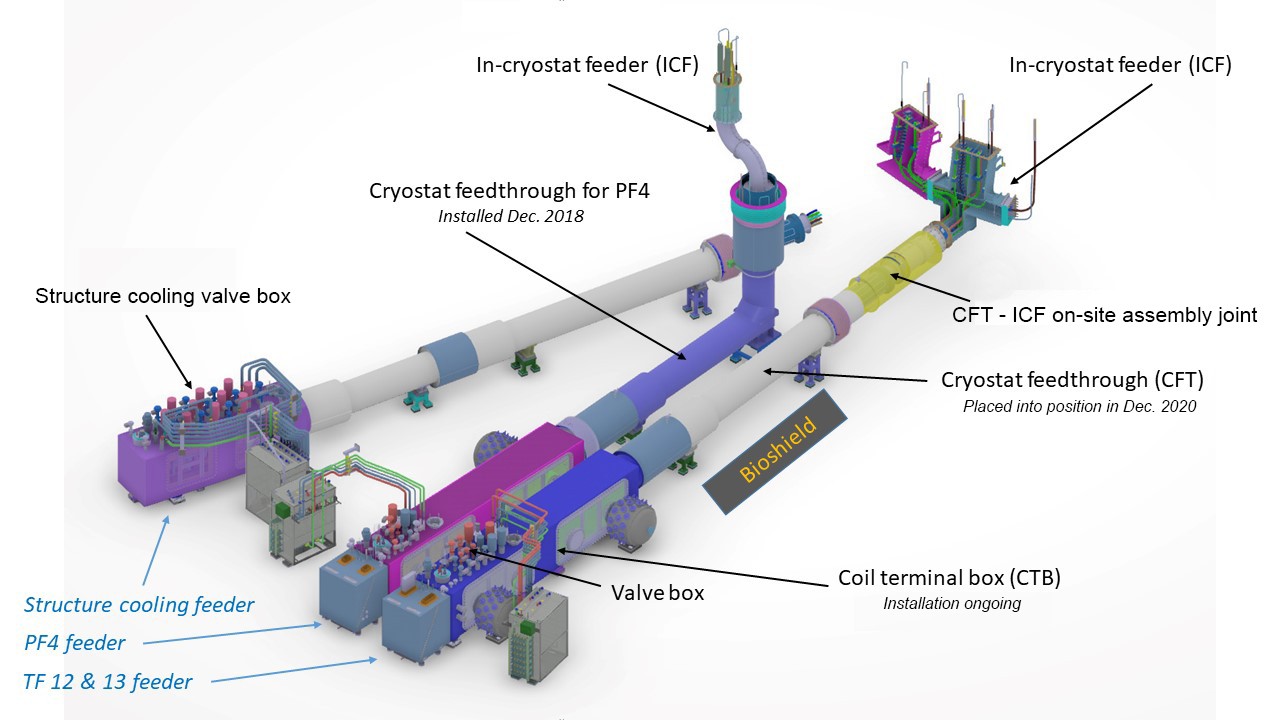
Whichever coil it connects to, a feeder is made of three main segments: a coil terminal box, a cryostat feedthrough and an in-cryostat feeder. Once assembled, these segments form a system 30 to 50 metres long that extends from the galleries to the heart of the machine.
The complexity inside defies description: busbars transporting current run alongside piping that distributes and recovers cryogenic fluids at different temperatures ... all carefully insulated by vacuum ducts and actively-cooled thermal shields. This multi-lane thruway into the machine also accommodates high and low-voltage instrumentation cables and hardware.
A little more than two years ago, in December 2018, the first magnet feeder element was installed in the assembly pit. Designed to serve poloidal field coil #4, one of the largest of the machine's ring-shaped magnets, the ''captive'' feedthrough needed to be brought into position before the completion of the cryostat base support ring.
In a delicate and spectacular operation, the 8-metre-long, 4.5-metre-tall, 7.5-tonne elbow-shaped component had to be introduced into the pit through the bioshield roof and inserted into the slim opening that had been left in the crown concrete for this purpose.
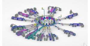
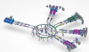
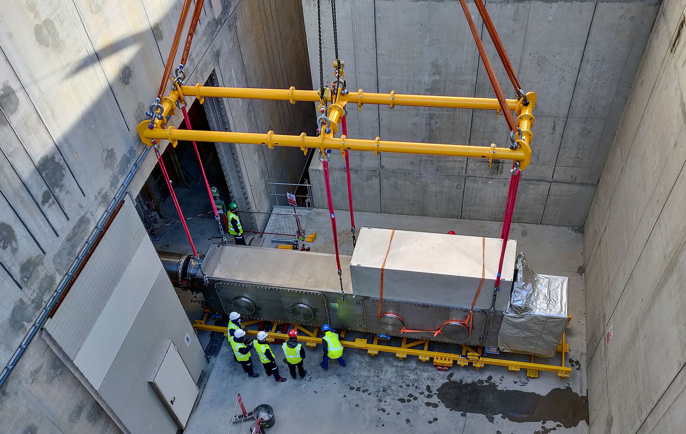
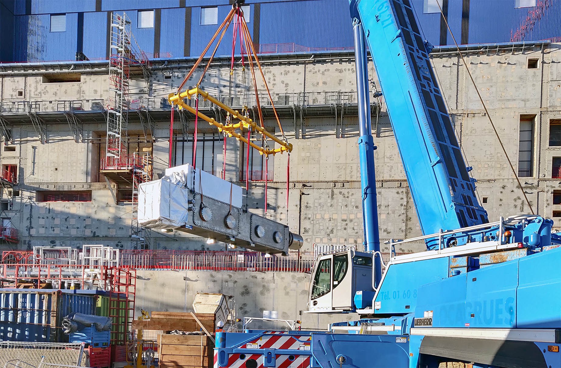
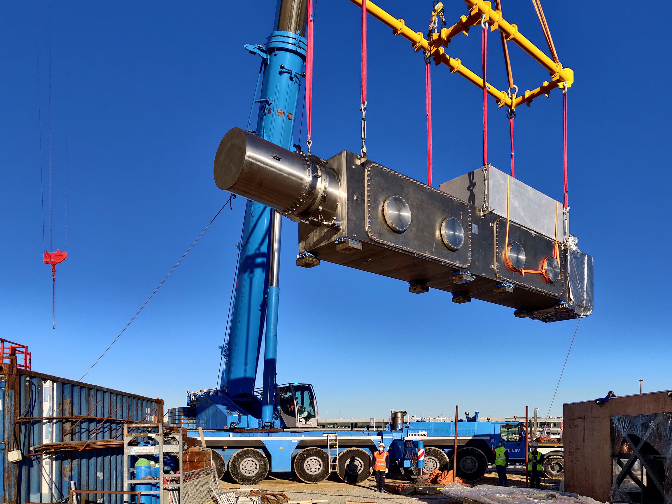
The three feeder segments that are now in place inside the Tokamak Building are just a fraction of the elements required for the complete system. As components are delivered from China, installation will progress clockwise, first at the lowest B2 level, which accommodates 21 feeders, later at the upper L3 level for the remaining 10.
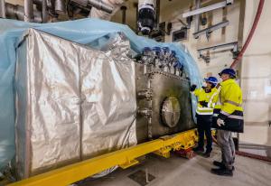
The feeder team has now established a robust installation plan and is proceeding on schedule. Next in line is the coil terminal box for PF #4, to be positioned parallel to the box recently installed, followed by the cryostat feedthrough and the valve box for one of the three feeders exclusively dedicated to cooling the coil structures.
* Of the 31 feeders to be installed (21 at lower level, 10 at upper level), two are exclusively dedicated to instrumentation signals and three to the cooling of coil structures. All others carry current and coolant to magnets.

