Subscribe options

Select your newsletters:

Please enter your email address:

@

Your email address will only be used for the purpose of sending you the ITER Organization publication(s) that you have requested. ITER Organization will not transfer your email address or other personal data to any other party or use it for commercial purposes.

If you change your mind, you can easily unsubscribe by clicking the unsubscribe option at the bottom of an email you've received from ITER Organization.

For more information, see our Privacy policy.

News & Media

Latest ITER Newsline

  • Poloidal field magnets | The last ring

    As the massive ring-shaped coil inched its way from the Poloidal Field Coils Winding Facility, where it was manufactured, to the storage facility nearby where i [...]

    Read more

  • Heat rejection | White "smoke" brings good news

    Like a plume of white smoke rising from a cardinals' conclave to announce the election of a new pope, the tenuous vapour coming from one of the ITER cooling cel [...]

    Read more

  • WEC 2024 | Energy on centre stage

    The global players in the energy sector convened in Rotterdam last week for the 26th edition of the World Energy Congress (WEC). The venue was well chosen, wit [...]

    Read more

  • Fusion world | The EU blueprint for fusion energy

    The EU Blueprint for Fusion Energy workshop, convened by the European Commission's Directorate-General for Energy, brought together key stakeholders in the fiel [...]

    Read more

  • Neutral beam injection | ELISE achieves target values for ITER

    Researchers at the Max Planck Institute for Plasma Physics in Garching, Germany, have generated the ion current densities required for ITER neutral beam injecti [...]

    Read more

Of Interest

See archived entries

Gyrotrons

India successfully demonstrates ITER power and pulse requirements

As a part of its in-kind commitments to the project, ITER India will deliver two radio-frequency-based power sources (or "gyrotrons") with state-of-the-art specifications (170 GHz, 1MW, up to 3600 s), as wells as four main high voltage power supplies (6MW, 55kV each) for electron cyclotron resonance heating. The deliverables also include the associated auxiliaries and a demonstration of complete system performance at the ITER site. One of the challenges of these complex high-power radio frequency systems is to establish integrated performance that is safe, reliable and easily repeatable despite working in a harsh electromagnetic environment.

The ITER India Gyrotron Test Facility has been used to successfully carry out the site acceptance of a test gyrotron to ITER power and pulse requirements. This significant achievement also confirms the successful commissioning of the megawatt-class, continuous wave test facility and validates the various auxiliary systems and their integrated performance. (Click to view larger version...)
The ITER India Gyrotron Test Facility has been used to successfully carry out the site acceptance of a test gyrotron to ITER power and pulse requirements. This significant achievement also confirms the successful commissioning of the megawatt-class, continuous wave test facility and validates the various auxiliary systems and their integrated performance.
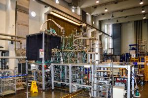
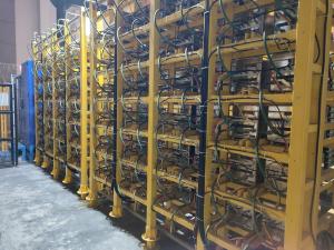
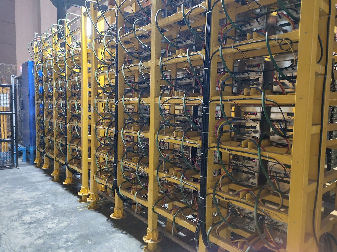
In order to validate and demonstrate the required integrated system performance, a megawatt (MW), continuous-wave-class Gyrotron Test Facility (IIGTF) has been developed at ITER India. The facility offers all the necessary auxiliary systems and services such as high-voltage and low-voltage power supplies; control, monitoring and protection systems; radio frequency diagnostic systems; cooling; and vacuum services. (These systems also serve as functional templates for actual ITER deliveries.) A test gyrotron with ITER-relevant specifications, along with a set of waveguide components including dummy loads, has been procured from M/s. GYCOM Russia and fully integrated with the test facility.

Extensive testing and validation of all interfaces was performed before the integrated testing. The main high-voltage power supply was validated for performance specifications including the Joule limit (wire burn test) to ensure the safety of the gyrotron during arcing.

The commissioned 6 MW main high-voltage power supply for the gyrotron cathode circuit at ITER India. (Click to view larger version...)
The commissioned 6 MW main high-voltage power supply for the gyrotron cathode circuit at ITER India.
After the interface validation tests, the site acceptance tests of the test gyrotron were successfully completed at ITER India. Output radio frequency power of 1MW at 170 GHz for 1000 s with radio frequency efficiency of about 50 percent was demonstrated during "power and pulse" tests, comprising five successful 1000-second pulses. Various detailed tests such as reliability tests (with a number of successive pulses of 500 s each) and power modulation tests up to 1kHz have also been performed. This significant achievement also confirms the successful commissioning of the megawatt-class, continuous wave Gyrotron Test Facility at ITER India and validates the various auxiliary systems and their integrated performance.

Test facility specifications:
Full-scale main high-voltage power supply:
- ratings of 6MW, 55kV
- based on PSM topology
- very fast time dynamics
- configuration compatible with ITER space and interface provisions
Anode power supply:
- ratings of 40 kV, 500 mA
- cost-effective
- developed using a COTS high-voltage power supply
- high voltage solid-state series switch to obtain fast time dynamics
Control system:
- a mix of custom designed and COTS products
- an operator-friendly software user interface for efficient control
- live monitoring of various field signals with fast (~µs) and slow (ms) protection interlocks
Various auxiliary power supplies to drive the magnetic coils and other sub-systems of the gyrotron
Active cooling water distribution system with industrial instrumentation for various flow parameters

Test gyrotron specifications:
Diode-type MIG gun with depressed collector configuration
Gyrotron tube:
- typical beam acceleration voltage of 72 kV
- about 43 A of beam current
- operating at a cavity magnetic field of about 6.62 T
Matching optic unit at the output of the gyrotron, coupling the radio frequency power into an evacuated corrugated waveguide line that could be terminated with either a continuous wave dummy load or with a short-pulse atmospheric dummy load by means of an SPDT waveguide switch


return to the latest published articles