Power to the plasma
6 May 2014
-
Lynne Degitz, US ITER
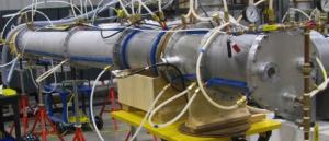
The resonant line test stand is used to determine the ultimate voltage and current limits of test articles, with voltages up to 35 kV steady state and 40 kV pulsed. The white tubing is part of the outer conductor water cooling connections. Photo: US ITER
To provide initial heating for fusion reactions, a combination of high-powered heating systems will be installed for the international ITER Tokamak, including radio frequency (RF) transmission lines that will deliver 20 million watts of power to the plasma. For perspective, that's about 400 times more power than a large radio station uses for transmission.
The US ITER ion cyclotron team at Oak Ridge National Laboratory has achieved high RF power levels in the laboratory and is working to finalize the design of the transmission lines and matching systems. Once the plasma is heated to full power, ITER will produce a self-heated plasma—which will be the first burning plasma created on Earth.
"We're trying to deliver every bit of power through our transmission lines that we said we would. They are designed to reliably carry double the initially available power, in order to accommodate a possible future power upgrade; we really need to deliver," said Rick Goulding, who leads US ITER's ion cyclotron heating (ICH) research and development program and is a physicist with ORNL's Plasma Technology and Applications Group in the Fusion Materials for Nuclear Systems Division.
US ITER developed a multi-function high power test stand at ORNL to confirm transmission line design and test specific components. Recent accomplishments include successful steady state high-voltage tests of candidate transmission lines at 35 kV, with 40 kV transient currents.
The team also successfully tested cooling the inner conductors of the line with circulating nitrogen at 3 atmospheres of pressure. Gas flowing between the conductors transfers heat from the internal inner conductor to the water-cooled outer conductor. The technique, chosen for use on ITER, keeps inner conductor temperatures well below the 150 degree Celsius operating limit.
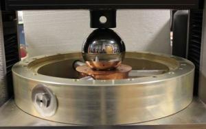
Tests of the US ITER conductor support spoke design involve placing a ball on the center hub and adding pressure. Tests show that each quartz rod is able to withstand about 500 pounds, which is more than three times the requirement. Photo: US ITER
The coaxial transmission line is basically a copper pipe inside an aluminum pipe, with inner and outer conductors separated by quartz insulators. Because of the high power requirements, the diameter of the ITER transmission lines is exceptionally large—about 12 inches—compared with low power transmission lines, such as those used for cable television transmission.
"Every component must have both a mechanical and an RF assessment," said Mike McCarthy, senior project engineer for the ICH team. To provide high RF power levels to ITER's plasma, the system needs to limit power losses, avoid electrical breakdowns and be sufficiently cooled.
In addition to testing performance, the ICH team, which includes staff from both ORNL and Princeton Plasma Physics Laboratory, needs to plan for how the transmission lines will be assembled in the ITER facility. To simplify assembly, the team developed a conductor support design that uses quartz spokes instead of a solid quartz disk.
"The advantage of the spoke design is that it can be pre-assembled before being joined to neighboring sections. The design also does not impede the flow of gas, so less pumping power would be required, and the spokes will absorb less RF power, leading to improved efficiency," Goulding said.
"Given the amount of assembly required for the transmission lines and that the assembly involves a worker elevated on a lift, we need to make our designs simple and sturdy. You have to think about the person in the field. Reliability, accessibility, maintainability and inspectability are core principles for us," McCarthy said.
Upcoming testing will assess more complicated devices, such as switches and power splitters. In addition to the resonant line, which creates a standing wave to achieve the highest possible voltage, a resonant ring has been built that distributes power more evenly along the test line—closely mimicking the heating that occurs in the bulk of the ITER transmission line. The resonant ring can be routinely operated at 6 megawatts for an hour; 17 long-pulse tests have been completed on the ring since 2012. As different prototype components are assessed, the ICH team has refined the test stand and its software controls to enable efficient, consistent, accurate testing.
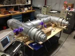
Future tests will assess the performance of hybrid power splitters, such as the above prototype, which are used to protect RF transmitters from reflected power. Photo: US ITER
"The transmission lines are expected to be the highest reliability components in the ion cyclotron system," Goulding said. Once the transmission lines are installed in the ITER facility, they will operate for many years.
The ITER transmission line design includes a tuning and matching system to minimize impedance discrepancies between sources and loads. The system also protects components from power reflected off the plasma by directing reflected power to a load that can absorb it.
The ITER Tokamak ultimately will rely on three external heating systems to bring the plasma up to full power: ion cyclotron heating, electron cyclotron heating and neutral beam heating. The US is responsible for both the ion and electron cyclotron heating system transmission lines. For the ion cyclotron system, the European Union will provide two antennas, while India is responsible for the RF power sources and high voltage supplies.
US participation in ITER is sponsored by the Department of Energy Office of Science and managed by Oak Ridge National Laboratory in Tennessee, with contributions by partner labs Princeton Plasma Physics Laboratory and Savannah River National Laboratory.


